By: Chris Popp
Screw jacks are mechanical linear lifting/lowering or pushing/pulling devices used in a wide range of industries to intermittently move loads into a desired position. The basic construction is a modified worm gear reducer with thrust bearings, for high axial load capacity, and a screw instead of an output shaft. They can be provided with acme screws for low duty applications, at a lower cost, or with ball screws for higher duty cycles. Sizes with force capacities from quarter ton to 100 tons are readily available.
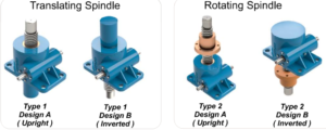
Two versions are usually offered. The translating version has the screw moving through the body to provide linear motion. The rotating version has a fixed length with the screw rotating to drive a nut up and down its length. While capacities are similar for both each has its advantages and limitations.
Integration Considerations – When planning for the integration of a screw jack, or jack system, into your machine design, there are 10 main parameters that should be taken into consideration.
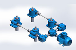
Design – Screw jacks can be used as an individual lifting mechanism or combined into a 2, 4, or more, “jack system” including all the drive, connecting, and safety components. The number of jacks required is primarily a function of the load configuration and dimensions. Wider loads may need more jacks for proper balance. But using smaller jacks may then be possible.
When determining which version of screw jack is best for the design consider that a translating version is most often used when the jack connection must stay on one side of the load. However, you need space opposite the load to make room for the retracting screw. The rotating version can provide a fixed length but the screw must fit though the load or be situated outside the envelope and, preferably, be supported at the top. The load then would be mounted to the traveling nut.
Operating Duty – Screw jacks aren’t usually designed for continuous duty like some other actuator types. The published ratings are typically based on the unit’s static capacity. The lift speed, the number of cycles, and the duration of operation all affect the available dynamic capacity, which will vary from application to application. Incorporating ball screws can increase the speed, cycles and duty, but at a higher cost than when using acme screws.
Travel Speeds – The travel speed refers to the distance traveled during a specified time, such as inches per minute. Options are offered to better match the requirements including different gearbox ratios and screw pitches. Ball screws can often move faster than acme screws but would often require more input torque.
Acceleration time would be a subset of this consideration. Screw jacks are typically used for generally positioning where very quick movements are not required. For high acceleration rates another linear motion technology would likely be more appropriate.
Mounting Accuracy – You should consider appropriate guides for the load to avoid excessive side forces. Special attention should be taken to assure the mounting surfaces and guides are parallel and without angular misalignment. This also applies to the drive and connecting components. Any misalignment will cause increased resistance and could result in rapid wear.
Long Screw Lengths – Relatively long screw lengths with loads in compression are subject to buckling which could limit the force capacity of a particular jack size. The translating version is especially susceptible to this consideration. This possibility can be virtually eliminated when designing for the screw to be in tension, where possible. Otherwise, if compression is necessary, you may have to up-size.
A different problem exists in the rotating version. Long length screws rotating at fast speeds can have a tendency to whip, or start to wobble outside the axis. This will limit the lift speed. You should always consider these issues, but especially for long travel applications. Catalog data is usually available to help determine when this might be an issue.
Rotation Avoidance – In the translating version it is possible that the load will spin, instead of lift, if the load is not guided. This is because the output reaction from input torque will follow the path of least resistance. Its easier to spin than lift. Guiding the load will eliminate that potential. If guiding isn’t possible then an anti-rotation option should be selected. This will include a device within the jack body that prevents the screw from turning, assuring axial movement.
Travel Distance – This is the amount of actual travel that is required, not necessarily the screw length. The screw could be much longer if the jack body is placed farther away from the load connection point and the retracted length dimension is greater than the minimum length allowable.
Take note to maintain safe clearance between moving and stationary components to avoid crashes. In the translating version consider escape protection to avoid the screw from coming out of the body during an unintended over extension. Limit switches to cut off motor power would be another option.
Accuracy Requirements – Accuracy requirements can include both repeatability and movement accuracy. When under continuous load, screwjacks provide excellent repeatability. An exception is when the load is relieved, such as in some horizontal applications. Clearances within the gearbox and screw connection would create a delay when retracting a load not constantly under some force.
Movement accuracy is largely a function of screw pitch accuracy and motor control. Ball screws typically have higher pitch accuracy than acme screws. However, even acme screws have an accuracy of around .008 of an inch per foot of travel, more than adequate for most applications.
Input Power – While a handwheel can do the job, most applications are automated, driving with either a standard AC motor or a servo motor. With an AC motor, an inverter or soft start is suggested to reduce starting shock load and reduce current draw. A brake may also be required if position over run is a concern. Servo motors can be programmed to compensate for these issues and provide faster and more accurate positioning.
A gearbox can also be added to the input to slow linear speed, when desired for smaller more incremental movements, and to add mechanical advantage for a reduction in required motor torque. Most product catalogs have formulas to help determine the input torque required based on the ratios and efficiencies of the worm ratio and screw pitch.
Testing The System – It is always a good idea to run the system first, without load, if you can. This will help identify any areas of potential misalignment. And when finally under load, a trial test at a slow speed will further assure there are no remaining issues that could de-rail optimal performance when the system is finally put into full operation.
While screwjacks are relatively standard catalog items, each application is truly unique and requires custom analysis to assure a successful integration. Considering these top ten elements during the system design process will avoid the majority of potential issues that could cause you problems later on.
(Chris Popp is President of C. Popp Enterprises, a manufacturer representative company. Chris has over 30 years experience consulting, selling, and applying linear and rotary mechanical motion control and power transmission components.)